BACK-UP BATTERY ALERT
A pair of DA-88s and DA-60s (the latter is Tascamís timecode DAT deck)
came to my shop with unusual problems. On power-up, one DA-88 lit
up like a Christmas tree but never initialized, the completion of which
occurs after the word "TASCAM" (or the message of your choice) scrolls
across the meter display. The DA-60 would accept and load a tape,
but go no further. It would not eject the tape.
At first I thought the problems were due to the careless installation
of new firmware, but that was not the case. After close inspection
ó and somewhat by accident ó it was discovered that all the machines had
a bit of crusty green schmutz around the backup battery. One battery
was surrounded by wisps of crystalline hairs ó way too alien for my taste!
I immediately got on the line to TASCAM hoping to score a few points
for tipping them off, but no one seemed aware of this problem. For
at least three of these machines, I knew for sure that their environment
was a bit hot under the collar. (See Tay Hoyleís article on air conditioning.)
It may very well be that the battery behaves under "normal" thermal conditions.
If your machine is over two years old and/or occasionally seems a taco
short of a combo platter, itís worth your while to inspect the battery
just to be sure.
Access the System Control board (SYSCON PCB) either from the rear of
the machine or by removing the top cover. In the same way the SY-88
sync card is installed, remove the black and chrome rear panel that covers
all of the circuit boards. A special tool is required to facilitate
card puling.
Or, for a simple inspection, remove both the top cover as well as the
copper chassis plate underneath (optional on some machines). Look
for a shiny, coin-like object centered on the left side of the SYSCON
PCB (the top most circuit board). If anything seems "foreign" in
this area, clean it up with an alcohol-soaked cotton swab (or two).
Be sure to wait for the alcohol to dry before powering back up.
Iíve been adding a little "insurance" to this procedure by installing
a piece of "Fish Paper" (MCM
part number 21-1125) under the battery plus a wire tie to hold it in
place. This will delay damage to the circuit board from alien substances
that are capable of eating the copper right off the board... Yes,
if the traces get eaten the board will have to be repaired and the battery
must be replaced.
RCA CONNECTORS
For another pair of machines, the complaint was simple: one of the balanced
inputs on the DB25 multi-pin connector was dead. The same channel
accepted signal at its RCA jack, so I checked the schematic to learn that
the output of the balanced input amplifier is routed through the RCA jack.
The input connectors have gold-plated contacts, but the "normalled" connection
was suffering from diminished contact pressure (see Glen Colemanís reference
to RST ó Relaxed Spring Tension ) which is possibly due to one or more
of the following:
· An RCA plug was inserted for a long period of time exposing
the contacts to airborne contamination.
· An oversized plug may have bent the normalled connection so
that it could not return to make contact.
· The spring material and/or the mechanical design of the jack
is flawed
The repair options are easy. The only obstacle are the number
of screws required to access the Analog Input A-to-D card. After
extracting the card, I used a very fine lapping film to burnish the normalled
contacts. (A "coarse" business card, cut into small strips and briefly
soaked in alcohol, will also do the job.) This made only a
slight improvement, so I inserted an RCA plug and applied pressure to the
normal, bending it toward the "closed" position. While this did the
trick, I chose instead to replace all four of the connectors. (TASCAM Part
Number 5330515400). Following is the step-by-step procedure of that
replacement. To view, open the graphic file "DA_88_RCA." Each
of the following numbers corresponds to that composite picture.
1. On the rear of the machine is a black metal plate that covers all
of the circuit cards. Once it is removed, the "A/D" card can be extracted
(Use the tool that came with the machine).
2. For each jack, only two of the three pins are accessible.
Remove the screws that secure the plate through which the RCA jacks protrude
and desolder the three connections that secure each jack.
3. To desolder, use either a desoldering braid or desoldering tools
(as shown). The former should be one-tenth inch wide and is available
in 5.5, 10, 50 and 100 foot lengths. (Ten
feet of Chem-Wick Lite, MCM part number 21-2190, is $6.)
Note: The thin copper shield between the back panel and
the jacks, creates a ground plane. Any ground potential problems
(from the external wiring) are routed directly to the chassis (rather than
through the PCB wiring) so that the internal ground will not be contaminated.
4. When soldering the new jacks, be sure to apply heat to one side of
the connector terminal while applying solder to the opposite side.
The terminal must be hot enough to melt solder on its own to guarantee
a good connection.
5. When the job has been completed, stand the board up on end and brush
denatured or anhydrous alcohol on the newly soldered area to remove the
flux. Inspect your connections with a magnifier.
6. A rear-view close-up of the RCA connector assembly. The jack
on the left shows a "closed" normal (no plug inserted) while the jack on
the right shows an "open" normal. Professional patch bays have far
more contact pressure than these RCA jacks, but even so, it is a good idea
to not leave patch cords in a bay for extended periods of time.
DIGITAL COPIES
Looking for a more affordable alternative to Tascamís Digital Interface
Cable (Model PW-88D, Part Number 5350515400)? While Tascamís price
is justified IF the harness is fabricated with low-capacitance
cable, with individual shields for each signal. PLEASE NOTE: Digital
equipment generates ó and can be the recipient of ó interference (hence
the FCC label on most gear regarding compliance with same). Below,
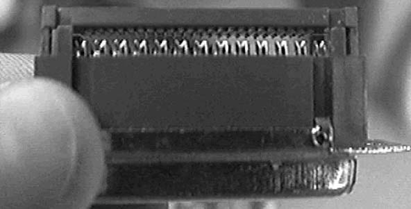
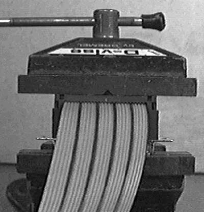
Figures
Two through Four indicate the use of a generic flat ribbon
cable which has been fine for my own applications up to 25 feet. However,
you might also consider these "more sophisticated" versions from DigiKey
(800-DIGI-KEY): A shielded, 25 conductor flat version (Part Number:
MC25R-X-ND) or an unshielded 2 conductor twisted pair version (Part Number:
MC26F-X-ND). Both are available from , as well as the connector (Part
Number CMM25G-ND). Approximate material cost: $25 to $35.

