Knowledge and powerDIY tips for reducing power-related noise in your studio.
By Eddie Ciletti
No matter what size of a studio you have, power-related noise can cause serious problems. The typical scenario in the personal studio goes something like this: the console is on one side of the room, and the keyboard and rack modules are on the other side. However, the system always has some sort of power-related noise, sometimes even with the faders down.
Power-related noises with analog gear are obvious and fairly easy to troubleshoot, because changes are instantly audible as you experiment. Hums and buzzes in the analog domain may be the only clue to mysterious problems in your digital devices; power-related noises may not be audible, but they can affect equipment performance.
When I used to make house calls for a living, more often than not, I was able to pinpoint and resolve such issues. Sometimes I offered advice over the phone, although it was never quite enough and my presence was requested anyway. Perhaps my explanation was too matter-of-fact, or the client never believed they had the power to fix many of the problems. However, you do have that power. In this article, I will address a number of power-related topics, from chasing down and minimizing a variety of noise problems to determining your power capacity and optimizing distribution.
If you choose to take the DIY approach, have respect for electricity: wear socks and shoes, don't stand in a puddle of water while working and always keep one hand in a pocket while probing (with a meter, for example). Basically, you don't want the jolt to hit you across the chest, from hand to hand or hand to foot. Once the electrical investigation requires going beyond your comfort level, find a knowledgeable electrician who is sensitive to the needs of a multimedia system.

Tree, Trunk, and LimbsRandomly plugging your gear into the most convenient outlets around a room can be the beginning of trouble. Power distribution in a home or office is not to audio standards and as such, there is an increased potential for noise when using more than one outlet.
The first thing I ask a customer is how many outlets are in the room and how many are being used. Then I suggest that everything be plugged into one outlet using the Tree, Trunk, and Limbs approach to power distribution (see Fig. 1). Think of the outlet as the bottom of a tree trunk into which is plugged an outlet strip. From that run the branches (more outlet strips). Plug your gear into the branches. If you had noise problems, this approach will most likely reduce or eliminate most of them.
Typically, when I pay a visit, at least two different outlets are being used. When asked why, the customer usually explains that he or she didn't think one extra outlet would make a difference and, besides, it was inconvenient to use only one outlet. I really don't want to charge my $300 minimum fee to grab an extension cord and reconnect the remote outlet strip. However, there are usually plenty of other things to sort out.
Although it may not be an ideal solutionand it does have limitsthe Tree, Trunk, and Limbs method distributes the same power and ground to all your outlet strips and gear, which is the ultimate goal no matter what size your system is.
Here Comes the Noise
Every electronic product you own dumps noise back into the power line. Power-related noises can be distributed by the power wiring or through the air by induction. The best receiver is the electric guitar, which acts as a divining rod for radiated electrical noises. That's because a single-coil guitar pickup and a power transformersuch as those found in amps, power supplies, and wall-wartshave something in common: both are coils of wire wrapped around a hunk of iron. A transformer radiates an electrical field, and a single-coil guitar pickup does as its name suggests.
A humbucking pickup has two coils, one of which is wired out of phase with the other. Any noise that is common to the coils and in phase is rejected. This type of phase cancellation technique is a common strategy for dealing with noisy lines.
Computer and video monitors also have coils, which coerce electrons into creating recognizable images on screen. Flat-panel displays have coils to generate voltage for the light source behind the panel. Both technologies radiate noise, so gather your audio harnesses with cable ties and dress them as far away from power sources as possible.
Light dimmers and fluorescent lights also generate Electromagnetic Interference (EMI), a very big term for a very annoying family of noises. Bill Whitlock, president of Jensen Transformers, recommends using an AM radio to track down noise sources, such as defective transformers in fluorescent light fixtures. Tune the radio to an unused frequency and walk close to any potential sources: the radio will pick up and amplify the interference.
While on the subject of noisy lights, the small, affordable dimmers you find everywhere do not belong in a recording environment. These super-efficient dimmers don't vary voltage to change bulb brightness, but chop up the 60 Hz wave instead: small pieces for dim, full wave for bright. If your light need "atmospheric control," chose a Variac-based dimmer. Although these are transformers and should be located away from sensitive gear, they don't generate high-frequency noise which tend to travel better through the air, just like Radio Frequency Interference (RFI).
Power transformers not only radiate energy into the air, but also into nearby metal objects, such as the chassis that houses your gear. Connect any two devices and noise current from one chassis will flow through the signal cabling to the other (and vice versa), specifically via the shield that is supposed to protect the signal wire(s) from radiated noise. All mic- and line-level audio cables have a shield, no matter what type of connector is at the end.
How the mating connector is mounted to the chassis determines a device's noise immunity. What you want is an electrical firewall, a safe place for the shield to dump its noise so it doesn't get into the box. (Once it is inside, it's harder to remove.) Renowned Toronto-based engineer Neil Muncy named this the Pin-1 issue, but it's not exclusive to XLR connectors. Quarter-inch, RCA and even Firewire and USB are all vulnerable IF the Shield / PIN-1 connection does not go directly to the metal chassis. This is the case for some connectors that are isolated from the chassis for ease of manufacturing. IF the path from "pin-1" to the chassis is through a printed circuit board trace, THEN all the noise infiltrates the ground scheme, where it can be amplified.
Balancing Act
An unbalanced audio cable has two conductors: one wire for signal plus a protective shield (as a multi-stranded wire-wrap, a braided "screen" or as an aluminum foil wrap). A balanced audio cable has three conductors: the shield plus a twisted pair of wires for the signal. In either case, the shield alone is not enough to stop a transformer's strong electrical field both for the aforementioned "pin-1" issue as well as the system's inherent ability to reject noise.
For example, If an unbalanced cable is too close to a wall-wart, the electrical field radiating from the transformer will pass through the shield and into the signal wire, producing a pronounced hum. Even if "pin-1" is correctly implemented, you can't change the laws of physics, in this case, breaking the law, a.k.a. death by Induction! But if the source and destination are balanced, the noise will be minimized as well as the circuit topology allows.
Balanced input and output circuits come in two primary forms: as active electronics or as a passive device known as a signal transformer. Transformers are more tolerant than poorly implemented transformerless designs. Both amplify a differential signal pair (that is, two signals of opposite polarity), but reject noise that is common to both signal wires. This relationship is known as the common mode rejection ratio, or CMRR. Look for it when checking out mic preamp specs; it also applies to line inputs, where its usually taken for granted.

In Figure-2, the audio signal is on the red and black wires, connected to pin-2 and pin-3 respectively. Notice that the two sine waves are out of phase with each other, but the red noise spikes (common-mode noise) are in phase. (Another common mode signal, 48V phantom power, travels over the yellow wire feeding the two resistors. It's called "phantom" because no additional wires are required to power the microphone.)There are two types of active balanced configuration: full balanced and impedance-balanced. We're all familiar with the former, which has two identical signals traveling down a shielded twisted-pair cable, one 180 degrees out-of-phase with the other. The amplifier driving each wire has a "defined" output or "source" impedance just as some vacuum tube guitar amps have a back panel selector switch to match the impedance of the amp with that of the speaker cabinet.
The math of amplification and rejection in an ideal balanced system is as simple as 1+1. Let's call the positive (pin-2) signal +1 and the negative (pin-3) signal -1. If each of these signals were on a mixer fader, the result of the addition would be zero, or cancellation. But a balanced input amplifier, also known as a differential amplifier, looks for differences in a signal. A differential amplifier subtracts what is common to both wiresin this case, the noise. But when it attempts to subtract two mirrored signals ([+1] - [-1]), the double negative becomes addition, yielding a two instead of zero.
Since an impedance-balanced configuration has only one modulated signal wire, it is crucial that the un-modulated signal wire be "sourced" by the same impedance. Don't get your panties in a bundle; it's just a resistor to ground. Matching these two impedances allows the differential amplifier at the other end of the cable to do its job. Maximum noise rejection "happens" when both wires are equally susceptible to noise. For really troublesome noises, a transformer at the input (destination) is more tolerant of circuit idiosyncrasies and can deliver 90 dB of CMRR.
In the Unbalanced World
If you are using unbalanced gear, the devicesincluding the mixershould be physically close together (preferably in the same rack), so that the interconnecting cables can be as short as possible. Long cables act as antennas for noise, so if the mixer can't be in the same rack, use high-quality cables with robust shields.
While most sound modules and keyboards are unbalanced, it doesn't hurt to route them to a balanced mixer using balanced audio cable. While it's far from an optimum solution, there will be some noise canceling benefit from doing so. In hostile environments, installing unbalanced-to-balanced converters at these sources will give you a fighting chance against noise. Use digital outputs wherever possible (it's worth the extra money to buy gear that has this option). And finally, make sure you have separate physical paths for power and audio. It's always a good idea to keep wall warts and power cables as far apart from audio cables as possible.
Ground Control
There has always been considerable fuss about the dreaded and misnamed ground loop, which is in reality the unavoidable ground current. As soon as a piece of gear is rack mounted, plugged in, and connected to another piece of gear, there will be ground currents in all cables. It would seem as if we are doomed at the start and that meeting any electrical code and achieving a quiet system are disparate goals, but that is not the case.

The most common bad-practice electrical activity is the misuse of the ground adapter as a ground lifter (see Figure-3). Use it only as a testing tool, never as a fix. Nothing is more permanent than a temporary solution.There are many so-called fixes applied to how the ends of interconnecting cable wiring are terminated. Tricks such as flying shields, where the shield at one end of the cable is not connected, complicate the wiring scheme. I prefer to keep things simple by connecting the shield at both ends to let the noise-prone gear reveal itself. Rather than compromise or complicate the system, the funky gear should be fixed, modified, or thrown away. There are several products that can interface unbalanced gear with balanced gear. Transformers may cost a bit more, but they are more effective.
Gear modifications, wiring and soldering techniques are outside the scope of this article but you are welcome to e-mail and send pix. If we get a good sampling of your problems (that can be fixed by remote control), perhaps they can be compiled into a future article.
System Overload?
Using the Tree, Trunk and Limbs method to solve power-related noises might also push the limits of the single circuit breaker now powering the entire system. For example, you might not want to turn everything on at once because the power-up current draw is much more than current draw once everything is on. The total power-draw for any breaker should be 75 percent of its rated value, such as 15 amps for a 20-amp breaker.
If you are concerned about overloading the electrical system or are popping breakers or fuses, there are two ways to determine your total power consumption. The easy way is with a clip-on ammeter (see Figure- 4). It eliminates all of the guesswork, but requires a professional electrician's respect for electricity.

Start by determining which circuit breaker feeds each outlet. Current is measured with a clip-on ammeter, while your gear is on and doing work. The red-orange jaws of a clip-on ammeter open so that a SINGLE wire from a breaker can be inserted. The jaws are then closed. Current is measured without making a physical or electrical connection, proving that wires radiate an electromagnetic field.After measuring all of the circuit breakers to which all of the audio equipment is connected, add up each reading. If the total is within 75 percent of 20 amps (15 amps or less), you are safe to plug all gear into one outlet using the TTL method.
Another way to determine your power consumption is to calculate using the specs from each device you use. Circuit breakers are rated in Amps (A), but appliance power consumption may be rated in amperes, watts, or volt-amperes (VA). Remember that power (in watts) equals volts times amps. The difference between watts and VA is the power factor. Unless the power factor is known, use the following formulas.
(watts to VA) watts/0.85 = VA
(VA to watts) VA x 0.85 = watts
Depending on your enthusiasm for calculating the total power consumption of your system, this might be the time to look in the yellow pages for a local electrician.
If the total draw of your system exceeds 15 amps, power down any items that do not seem relevant to the problem but leave everything plugged in to maintain the conditions that may be causing the hum or buzz. We don't want to pop the breaker from excess current and, as mentioned, the goal is to localize / weed out the noise prone gear. If your system requires more than 15 amps and you have the luxury of rewiring, put each outlet on its own breaker with its own ground wire back to the box using the isolated ground outlet detailed in the "Faulty Outlet" section.
Another warning sign that you are pushing the power strips and extension cables to their limit is when power plugs are warm to the touch. However, plugs can become warm if the wires in the plug or socket are not secure. Molded power plugs should have spot-welded connections. Unfortunately, cheaper products only crimp the wires to the prongs. Over time, and through repeated cycles of heating and cooling, oxidation builds up resistance at the junction of wire and prong causing the plug to warm. The same is true for outlets that have lost their grip.
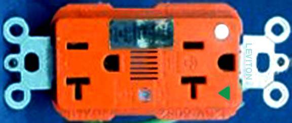
Replacing power strips is easy, but you should also have your electrician inspect all power outlets, tightening or replacing them as necessary. Use either heavy-duty outlets or the orange hospital-grade power outlets as shown in Figure-5.
Faulty Outlet?If plugging everything into one outlet lowered the noise, then your problem may be related to the wiring in one of the outlets. Use an outlet tester, available at most hardware stores, to confirm that your outlets are correctly wired (see Figure-6). An outlet tester can detect gross wiring errors, although problems are typically more subtle than that.

Figure-7 shows how an outlet should be wired: black for hot, white for neutral, and green for ground. Neutral is also referred to as the return wire that completes the circuit.

In the wiring of a standard household electrical socket, ground travels through the round prong of a power plug. It's important to note that ground is there for safety purposes, not for providing low-noise audio. Standard outlets receive ground when the mounting screw touches the outlet box. Hospital-grade orange power outlets have a ground screw that is isolated from the mounting flanges (see Figure-5, above). This provides an isolated ground wire all the way back to the breaker box, rather than relying on potential interruptions such as loose screws at each conduit extension or the spiral metal jacket of BX cable.The route from orange outlet to a dedicated ground wire terminating into a 6-foot spike set into damp earth requires extra time and money, but it's not cost prohibitive. That said, it still doesn't ensure a quiet ground connection. The isolated ground wire is easily contaminated by noise currents in the black and white power wires because of their close proximity within the conduit. To prove this, I have experimented with running ground wires outside the conduit with greatly improved results, but, I have never investigated the electric code to know how this might be legally and safely implemented. Consult your local electrician.
In a typical home or office building, outlets are daisy-chained, and every loose connection between themwhether it is on the hot, neutral, or ground lineis a potential noise source. With the breaker off, each outlet should be pulled, inspected, and tightened if necessary by a licensed electrician.
In the breaker box, there should be two buss bars, which are hunks of aluminum, copper, or copper-alloy, tapped with screws for multiple wires (one bar for neutral and one for ground). Because every connection is a potential noise source, all of the buss bar screws should be checked and tightened if necessary (see Fig. QQQ).
As mentioned earlier, all of your gear reflects noise back into the power wiring, but if a more serious variety of noise is coming from outside your facility, the best way to tame it is with an uninterruptible power supply (UPS). A UPS converts AC power to DC by charging up batteries instead of capacitors, then converts the power back to AC. Not only is it effective at cleaning up noise, it also provides a safeguard against spikes and power failures. Remember that isolation and balanced power transformers do not filter noise, and to be truly effective, they must be properly installed where power enters the building.
I'm not a big fan of rack-mount voltage regulators and surge protectors. I prefer a UPS to do all that, as well as provide back-up in case of power failure. Not every model of UPS offers voltage regulationsuch as the American Power Conversion (APC) Back-UPS Pro line at www.apcc.com. But unless you live in an area with wide voltage swings, from brownout to danger, most of your gear has sufficient internal regulation. Most computers, for example, will run on 90V to 200V by design.
Heavy Metal Noise
Balanced power enters the home as 220V to 240V. Neutral comes from a center tap on the utility pole transformer, hence our 110V to 120V standard outlet power (see Figure-9). Neutral is tied to ground as it enters the home, but it tends to get dirty from all the appliances that are constantly switching on and off (microwave oven, fridge, washer, and dryer). It's even worse in a commercial building, which may have elevators and HVAC.


A 1:1 isolation transformer can help avoid the neutral noise by taking the 220V on its primary side. A new, clean neutral is then established on the secondary side for your audio power network. It's not a big deal to add one, but it's not a DIY project. As for balanced power, I have mixed feelings. It is somewhat effective, but not a panacea. Understand that I am not looking to modify your gear, but I can say than when noise-prone gear is "fixed" it sounds better too.Like the aforementioned impedance-balanced method of interconnecting audio gear, to be effective, Balanced Power requires a similar form of "impedance equity" in the power distribution system. Not all gear treats incoming power in the same way. A customer once bought a balanced power transformer because he had read in a magazine that it was a miracle box. When it showed up, it was too heavy to move and there was nowhere to put it. However, the real problem was summer brownouts, something a balanced-power transformer doesnt fix.
All transformers that are big enough to run an entire recording areaincluding lightsare big, heavy, and potentially noisy. They make physical noise as well as radiated noise so location is key, preferably where the power lines enter the facility, as far away from guitars and analog tape machines as possible. Although there are project-studio-sized transformers available, do yourself a favor by consulting an electrician about the best solution for your needs, as well as the optimum place to install a transformer if you really need one.
Floating Interference
RFI and Television Interferencealso known as RFI/TVIis a lot more squirrelly than your garden variety hums and buzzes, but the root of their evil is the same. RFI has an obvious sound. TVI, on the other hand, sounds very similar to a power-buzz, except it tends to vary in character, with a phase-sweeping quality. That is because TVI is video picture noise with a 59.95 Hz fundamental0.05 cycles per second less than 60 Hz AC power. Hearing them together causes the slow phasing artifacts.
 |
 |
One of the DIY solutions for eliminating RFI/TVI is the ferrite clam, which is easy to apply to cable ends (see Fig. 10a and 10b). You have probably seen these before on computer video-monitor cables, hidden under shrink tubing. In essence, the ferrite acts as a near-short circuit at frequencies from 1 MHz to 100 MHzexactly where you need them to work. The clam shell filter comes in various sizes to accommodate wire thickness. Guitar cables are also good candidates for ferrite clam filters.Another RFI/TVI fix requires the most basic soldering and mechanical skills and it applies to the male end of an XLR cable. A standard 3-conductor XLR configuration has shield/ground on pin-1, signal high/hot on pin-2, and signal low/cold on pin-3. There is also a fourth pin that connects directly to the chassis by means of the connector shell. XLR pin-1 is supposed to go directly to chassis, but when it takes a more circuitous route, high-gain mic preamplifiers see not only hum and buzz but also RFI/TVI. If adding a jumper wire from pin-1 to the chassis-lug fixes your problem, you may want a technician to go inside the box to make it permanent.
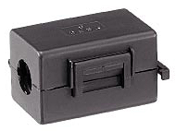
Video and Computer monitors have their own way of displaying hum, as a rolling horizontal bar. You will typically see and hear hum when integrating a cable TV box into an audio system because the cable is grounded when it enters the building and this will not be at the same potential as the audio system ground. As a result, current will flow. The fix for that noise is to insert an isolation transformer between the cable wire and the cable box or video recorder (see Figure-11).

Dress RightCable quality can also affect noise reception in hostile environments. Typically, multi-channel snakes have a foil shield with a drain wire. These may be acceptable for line-level applications, but for mic and unbalanced lines, a heavy copper braid or wrap is better because it reduces noise by 15dB. Canare Star Quad cable, which has a braided shield and two pairs of signal conductors, is best, offering a 40 dB reduction.
Now it's time to address the wiring in the rack. Here it would be helpful if all manufacturers adhered to a standard location for the power connector. When applicable, I place a vertical power strip on the cabinet side that has most of the power inlets, using short, 18-inch IEC power cords. You should avoid coiling any cablespower as well as audioto minimize noise generation and pick-up. Don't forget to use cable ties to bundle audio cables on one side of your rack, and power cables on the other side.
The Knowledge of Power
Understanding potential noise sources and using the Tree, Trunk and Limbs method of power distribution should allow you to identify, and in most cases reduce, the major problems in your system. However, there are situations that require the combined support of an experienced technician along with an understanding and sympathetic electrician, one that may also be a musician, for example. Although it may be more expensive than the DIY approach a system that is consistently safe and quiet will be worth the investment.
[bio]
Eddie Ciletti provides childcare by day, winds up by repairing and modifying gear (www.tangible-technology.com), and unwinds by editing a new instructional music video. He also teaches recording and maintenance one day a week at www.iprschool.com.
[sidebar 1]
Plug Aerobics
One of the most deceptive noise challenges is an audio system that began life "quiet enough," but over time gradually becomes noisier until things eventually get out of control. There are numerous possibilities, but it doesn't hurt to disconnect everything and clean the connectors with 99 percent isopropyl alcohol. Then, apply a contact cleaner using a cloth or cotton swab. Avoid spraying the cleaner on anything because it will attract more funk than is washes away.
And while beyond the scope of this article, the propellant that forces the cleaner/lubricant out of the can is so cold that water vapor will condense on cold connectors causing additional corrosion. Circuit board edge connectors are particularly vulnerable because even when gold plated, the underlying metal is copper and we all know what happens when this metal attempts self-preservation.
[sidebar 2]
Buzz by Design
Noise-prone equipment is not necessarily due to poor design. More likely, it is due to shortcuts taken to aid mass production. Eighties-era gear often used plastic-insulated jacks mounted directly to a printed circuit board (PCB). As a result, the noise was dumped directly to the PCB ground, to which many high-gain amplifiers are referenced, instead of being stopped at the "firewall," the metal chassis that houses your magic circuitry.
For an example of good design, check out any Mackie mixer and notice that all of the 1/4-inch jacks have metal threads and a metal nut securing them directly to a metal chassis. Minimizing noise susceptibility is almost that simple and it certainly starts there.