An EQ Magazine Maintenance Column from the May'95 issueTRUE CONFESSIONS: "I made the hum go away!"
©1995 by Eddie CilettiAnyone who has ever embarked on a studio construction project has encountered the phrase, "Star Grounding," a process that starts with the establishment of a central ground point (a copper spike in the earth) and ends with each piece of gear attached to it. The following modification incorporates this concept into the internal wiring scheme of a mixer, in this case, the Soundcraft 200B series.
By individually grounding each module, internal hum can be reduced up to 12 dB on a fully-loaded 32-input frame. The new Soundcraft Delta series incorporates this feature as does Studiomaster. I got the idea from a Neve 8100 series console. It can also be adapted to other mixers, but is most easily visualized and implemented on the 200 series. Whether you are attempting this project solo, or with the aid of an experienced technician, be sure to locate the operator's manual and schematics. The block diagrams provide an overview of the signal path while the schematic diagrams detail the circuitry and wiring. (At the bottom of this page, Table One shows what tools and materials are required to get started.)
BEFORE GETTING DOWN TO BIZ
Before dismembering the console, number each module with a china marker. Then, grab a notebook (virtual or otherwise) and detail any problems such as intermittent connections, scratchy pots, faders, etc. Use a Pozidrive Phillips screwdriver to extract the module screws without damaging them. (Using the wrong tool, or a damaged one, can make the simplest job difficult.) Place all hardware in a spill-resistant container.
One at a time, carefully disconnect each module. At the top of the channel modules are the mic, line and insert connections. The lower ribbon cable provides power, ground, solo and bussing functions to all of the modules. The goal is to provide a separate ground to each module. Since the beauty of this console is its modularity, the trick is to integrate the mod without sacrificing serviceability. Part of what we will be doing is cutting and peeling a ribbon cable, which, in practice, actually is a fairly easy thing to do. Luckily, the last four wires of the ribbon harness are ground.
Important: Pay especially close attention to the wiring of the group, aux, mix and monitor modules. You may even want to label each ribbon wire and its associated connector before disconnecting anything. Use a Sanford "Sharpie" felt-tipped marker so it wonít rub off. Also, while you have the console disassembled, check all modules for cold solder joints at each switch and pot. (A magnifying lens and good lighting is helpful.)
UNDER THE HOOD
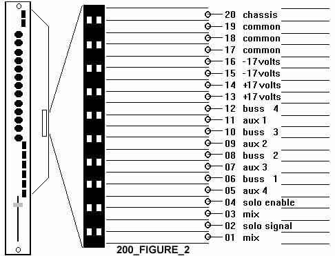
The power distribution harness is opposite the power connector located on the rear panel of the console. The green wires distribute ground to the factory buss bar and the lower ribbon PCB. From here, power is fed to all of the modules. An exploded view of the lower ribbon connector and cable is detailed in Figure 2. The pin numbers are not specified on any of the schematics. The color stripe at the edge of the ribbon cable, plus an arrow embossed on the male connector (toward the fader), indicate pin one.
FUN TIME
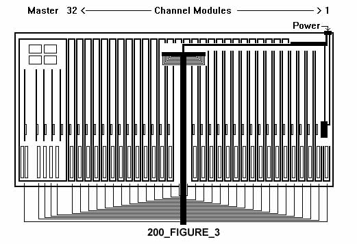
Place the modules in reverse order, face down on the console frame, starting with channel one to the far right. (See the drawing in Figure 3.) Once all the modules are in place, reorient and connect only the lower ribbon cable. Indicate the cuts to be made with a black Sharpie™, but do not make any cuts to the ribbon at this time. There will be one cut for each module, each of the four group modules and the stereo mix module. The monitor module can be fed ground through the ribbon cable. Again, donít do any stripping or soldering yet! (You donít want any metal bits to fall into the modules.)
Route a ground wire from the furthest module to the location where the new Buss Bar will be installed. (I chose the rear center of the console frame.) Bend at a right angle using an upside down module to hold it in place and leaving enough slack so modules can still be removed for service. Then, cut enough ground wires to this "universal" length keeping in mind that, if speaker cable is used, only one cable is required for each pair of modules. Once a ground harness is cut and dressed, secure it with wire ties. Disconnect the ribbon cable, remove the modules and install the Buss Bar. (See Figure 4 for a look at the installed Buss Bar with the ground wires connected.)
Now itís time to make a mess!
THE MODIFICATION: HEAT YOUR IRONS
Place the ground harness into the console frame and dress the end that will go into the Buss Bar and mark where the lengths should be cut with a Sharpie. (Make all cuts, remove insulation, twist the strands together and apply solder to "tin" both ends of the harness. (Please, do all of this work outside of the console!)
Note: 16-gauge speaker wire is recommended because it is easy to find. When prepping the other end of the ground harness, be sure to twist each pair (to conserve space in the buss bar) and tin.Then, insert the ground wires into the Buss Bar. Be sure the screws are snug.
After all of the cuts to the ribbon cable have been made, carefully separate each wire about two inches and strip about 3/4 inches of insulation. The outside wire, number 20, is the "chassis" connection. (The ribbon cable should have a colored stripe to designate Pin 1.) Twist it together with 17, 18 and 19, then tin. With the ground harness in place, there should be enough slack to dress the wires intended for each module over the front arm rest so that soldering to the ribbon cable can also be done outside of the console frame. Remember the shrink tubing before soldering the four ribbon wires to the ground harness!
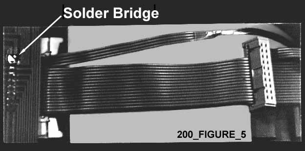
On the Input Channel Module printed circuit board (PCB), link pin 20 of the ribbon connector with the other three by forming a solder bridge. (Notice the shiny spot just to the left of the four ribbon wires in Figure 4.) While your iron is hot, be sure to inspect the solder joints at all connectors (also check the connectors on the console's back panel) and frequently used controls. Click here for the "Soldering Tips" article to learn how to spot and repair "cold" solder joints. Figure 5 below shows what the mod will look like right side up.
ITíS A WRAP
Be sure to carefully inspect your work, especially the modules, with adequate illumination. The modification is safe and easy so long as you cut the ribbon properly. (Remember the carpenterís rule: "Measure twice, cut once!") Power up the frame once without the modules and measure the supply voltages at the power distribution PCB. Then reinstall the modules. Any hum that originated from the console should now be well below the hiss. Clients who received this treatment always commented that the low end seemed tighter and that high-frequency imaging improved.
There is also a gain structure modification that is quite simple. The gain mod has you setting ALL the output jumpers for "-10" operation but running ALL the faders at Maximum. If you have a manual, you'll see they have a very strange and noisy way of adding GAIN to achieve "+4" operation. This approach quiets the output amps.
Click here for and article about OpAmp and Capacitor upgrades


