The Art of Dynamics: From a Purr to a Roarwritten for the March Issue of EQ Magazine
©1998 by Eddie Ciletti
Studies of ancient cave paintings reveal that dynamics processing existed even in prehistoric times. One series of images begins with a man and a child in close proximity to a lion. With hand stretched out, the child is ready to apply affection, but, just before it can say "nice kitty," the parent quickly plucks the toddler from danger. After the chase, our ancestors are physically safe albeit still within earshot of the great cat. As the lion roars, both man and child have hands securely placed over their ears, equal to a brickwall limiter, with infinite-to-one ratio and threshold set to 50 dB SPL. Tests are now underway to determine the unprocessed dynamic range of the lion, from a purr to a roar.
In more recent times, rodeo-style gain riding began with the ear as detector, the hand as control device and the volume control as attentuator
THE CLASSICS
This months exploration into the blood and guts of dynamics processors begins with two classic cousins the Teletronics LA-2A ( Figure 1 ) and the Universal Audio LA-3A. Since both of these "Leveling Amplifiers" rely on the same optical attenuator, their response to dynamic challenges is nearly identical. Some of the sonic differences can be attributed to the implementation tubes in the LA-2, transistors in the LA-3. "Reproductions" of the LA-2A, most notably the ADL 1000 and ADL 1500, have the same exact circuitry yet sound different. This is primarily due to the choice of input and output transformers. Different, yet perfect for mix buss homogenization.

Figure 1
FET CHANCE
Of course there are many ways to dynamically skin a cat. (Any connection with the opening paragraph is "purr" coincidence.) Classics like the UREI 1176 ( Figure 2 ) and the Audio Designs Compex-Limiter, along with the more modern Empirical Labs Distressor, all use the Field Effect Transistor (FET). In the early seventies, dbx designed and built a transistorized Voltage Controlled Amplifier (VCA) as the gain manipulating device for their compressor/limiters. The VCA also played a key role in their noise reduction system.
|
|

Figure 2 AND THEN THERE WAS LIGHT
An optical attenuator is essentially a light-sensitive volume control. In the mechanical version, the knob (a.k.a. the control device) is connected to a wiper which "divides" one resistor into two parts two resistors of equal value yield an output voltage half that of the input. Are ya ready? Lets go into the light
A photo-resistor changes its value with light: high when dark, low when bright. The filament in an incandescent lamp is too slow for transients, with a delayed "release" thats too long to be useful. Photo-resistor response varies, but most have a "natural" medium-fast attack and a non-linear release thats initially fast, then slow. Achieving the desired characteristics requires testing and grading.
A LIGHT LUNCH
For speed, an LED light source might be the choice now, but the early sixties predates their birth. Neon bulbs have existed for years but these devices are not linear. The answer came from technology employed by the aviation industry called "The Electro-Luminescent Panel." A high impedance device, the "EL" consists of a capacitor sandwich sealed in a clear, flexible plastic (hold the mayo).
EL panels can be made into all sorts of shapes, a trait particularly well-suited for illuminating aircraft instrument panels especially "Warning" indicators on planes because they dont burn out. Available in a variety of colors (photo-resistors are color sensitive), ELs are currently used to back-light the LCD displays used in laptops and other fine electronic toys.
OK, LETs SPLIT
After a signal enters any dynamics processor, it splits in two. One half is routed to the gain manipulating device while the other heads off to the "detection" circuitry each with its own volume control. In the "optical" case, an amplifier drives the EL panel. Louder equals brighter equals more attenuation.
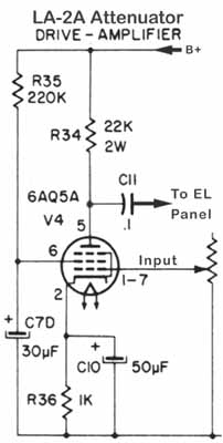
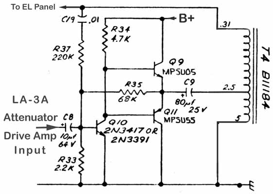
Note the variation in drive circuitry between the LA-2 ( Figure 3 ) and the LA-3 ( Figure 4 ). Both are simple amplifiers, but the transistor circuit uses a step-up transformer to generate the necessary drive voltage for the EL panel. You can buy an EL panel at a hardware store in the form of a "night lights." And yes, it really does take 120 volts AC to get em going!
 |
 |
|
|
Unlike the optical attenuator, both an FET and a VCA require a more sophisticated "detector" circuit. The audio signal (AC) must be converted into a corresponding DC voltage and then further manipulated by the more familiar, attack, release, ratio and threshold circuitry. Drums and vocals are diverse sonic challenges that require additional detector sophistication. Features like Peak and RMS detection make the processor more versatile.METER MAID
With any dynamics "module" the great question is whether the metering accurately reflects the processing being done. You may have noticed that the optical attenuator has at least two photo-resistors, one for gain reduction and one for metering same. LA-2As become particularly inconsistent because their photo-resistors will age differently. In addition, when the meters "0VU" setting wanders, check the "voltage regulator," which for this circuit is A NEON BULB!!! Remember I mentioned that the neon bulb is non-linear? Well, once "fired" it acts like a zener diode, clamping at 65 volts. Neon also degrades with age and should be replaced by a zener diode. See Figure 5.
|
|

Figure 5 How many engineers does it take to change an optical module? Just one! For a new part called the T4B all it takes is a phone call to JBL (818-895-3417 or 818-894-8850) and $160. An alternate source for new ($145) and rebuilt ($60) modules is ADL (914-256-0032).
BASIC MAINTENANCE AND OPERATIONAL TIPS
Here are three quick LA-3A tips to share. First, pop the lid and spray a little Caig DeOxit into the GAIN switch exercise vigorously then set to 30 dB. Using the 50 dB setting with a nominal "Plus-Four" source may overload the input transformer, unless youre trying to use the LA-3A as a mic pre!
While the lid is open, check R14. On the schematic, this part is listed as 220-k-ohms. Changing the value to 47-k-ohms will reduce the gain and some noise as well. Youll have to run the Input Level at a higher setting, but thats OK.
Like any transformer-based device, the LA-3A was designed to drive a 600-ohm load. Unless you are consistently patching into a Pultec, an old Neve console or some equally vintage piece, it is highly advisable that you put a 620-ohm, ½-watt resistor across the output terminals of all your transformer-based gear! There will be a sonic difference.