ALTERNATE REFERENCES

Test tapes, if you can afford them, should not be played on a funky transport. You can and should make reference tapes on several properly operating machines. Choose the maximum length recommended by the manufacturer, record a 40-Hz tone at about -20 dB from end to end. Indicate the date, make, model, machine serial number and, if your deck has an error rate display, make a note of that as well. 

THE "OTHER" GOAL

To observe the idiosyncrasies of tape path, one must learn to use an oscilloscope, be familiar with the wave forms (what "normal" is) and have the proper mechanical tools. (See the sidebar, "Key Tools.") To discern good path from bad path requires familiarity. Once understood, you will be able to determine whether the culprit is the tape or the machine. The slightest tweak can make a poorly recorded tape playable, but if the machine must be returned to working order, it is critical that your tools be in new or perfect condition. Don’t be cheap or careless! Buy high-quality tools and be good to them. 

COMMON GROUND

Just to avoid confusion, note that the VHS transport found in the Alesis ADAT and the Fostex RD-8 transport are identical. The following products all use a similar Alps 4mm transport: the Tascam DA-30 and DA-P20, the Fostex D-20 and the Casio DA-7. Panasonic manufactures their own transport and use it in their SV-3200/SV-DA10, SV-3700, SV-3800, SV-3900 and SV-4100. This mechanism is also found in the Fostex D-10. 

GAINING ACCESS TO THE TRANSPORT AND TEST POINTS

Simply removing the top cover will provide visual access to most machines. In most cases the loading mechanism must be removed. Test points for full-size Panasonic and Tascam models is fairly easy. Older Sony and all portables require wires to be soldered to the circuit board on the bottom of the machine.. 

HINT: Buy a Service Manual!
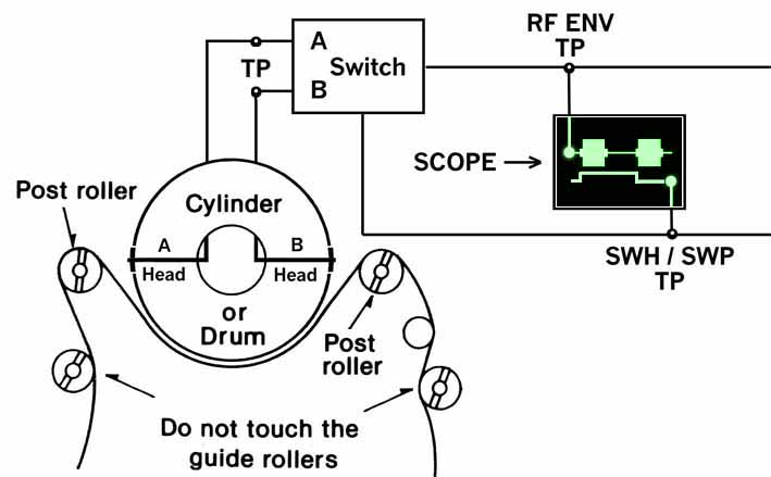
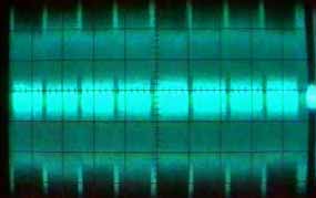
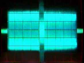
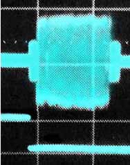
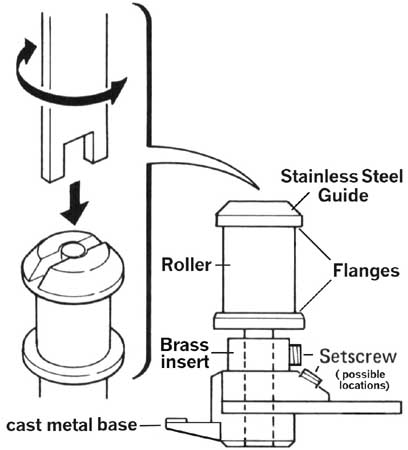

Figure 3: Connecting the ‘scope to the Test Points

Figure 3 shows the location of both the primary mechanical adjustments (post rollers) and the electrical test points. (See manual for location.) All machines have at least two heads in the upper drum that are located 180 degrees from each other. The RF (radio frequency) signal from each head must first be amplified, then combined into a single channel by an electronic switch that receives its cue from the SWP/SWH signal. 

1. Attach a probe from the test point (TP) labeled RF/ENV to Channel One of the ‘scope. (See the service manual for specific locations.) The RF signal from the head preamp may be sensitive to cable loading, so make sure your probes have a "X10" setting. (The built-in attenuator will decrease the signal at the ‘scope, but the increased probe impedance will not tax the source.) 

2. From the TP labeled SWH/SWP, connect a probe to channel two. This signal is a square wave that can be used to check the timing of the head signal as well as serve as the trigger source. (The external trigger input can also be used.) Press Play to view the RF envelope. 

3. Set the TRIGGER SOURCE on the ‘scope to channel 2. Adjust the sensitivity of both channels, as well as the sweep rate, as per the instructions in the manual. (These values vary with machine and format.)

WHAT IT’S SUPPOSED TO LOOK LIKE
 
Figure 4-A
Figure 4-B
Figure 4-C

 
Figures 4-A, 4-B and 4-C show RF envelopes from the SVHS, 8mm and 4mm transports, respectively. The DAT / 4mm picture also includes the head switching signal on the lower trace. For an added kick, users checking their DAT decks should try writing a start ID while monitoring the oscilloscope. Note that only the outside areas of the envelope get recorded.


MECHANICAL ADJUSTMENTS

Figure 3 showed the overhead view of the primary mechanical adjustments for all helical scan transports.  Unlike Analog tape decks, no adjustments are made to the helical head assembly.  In the Helical system, the Loading Guides, or Post Rollers, serve double-duty.  When in the unload position, they are relaxed and sloppy.  This is normal!   Once the tape is wrapped around the heads, however, the guides are spring-loaded into the "V" block.

Figure 5 shows the Slant Block Assembly , which consists of a cast-metal Base and a stainless-steel Angled Post (not shown). A machined Brass Insert with set screws is press-fit into the Base.  The guide assembly is constructed from four pieces: the upper flange, the lower flange, a nylon roller guide (sometimes ceramic) and the screw shaft.  Do not attempt to turn the guide without loosening the set screw.


Figure 5: The Slant-Block Assembly

EXPOSING THE SONY-PANSONIC MYTH

Some Sony machines have no set screws.  A spring inserted between the guide and the brass insert holds the alignment. ( The Alps transport in Tascam's DA-30 MKII and DA-P1 portable uses plastic slant blocks as well as spring-loaded guides.)  Many Sony "Base" blocks have such terrible mechanical tolerances that the angled post and the brass insert are not securely held.  These machines are notorious for not holding an alignment, creating the myth that Sony and Panasonic align to a different standard.  NOT TRUE!  If the Brass Insert and Slant Post are glued to the Base (when disassembled from the mechanism), the machine will hold its alignment.  Most set screws are either phillips head or .89mm metric hex.  Sony portables, however, use flat-head set screws horizontally mounted, rather that the preferred 45 degree angle.  These are not only near-impossible to access but they often come loose. 

MORE INFO

For more information about helical scan transports and the DAT format, I recommend the Panasonic Technical Guide (Order # AD9009273G0).  Panasonic is very difficult to reach by voice (800-833-9626) but communication via fax does work (800-237-9080).  In addition, the Alesis service manual is extremely thorough. Roughly the size of a phone book, the service information is well written, it includes theory and software history plus hardware tweaks from the dawn of ADAT time. 

Tascam’s dual-language (Japanese/English) manuals are pretty thin considering the power of their products. Much of the real information is unpublished. Hopefully this site will fill in some of the gaps.


SIDEBAR: KEY TOOLS and TEST TAPES

For this project, the key tool is a dual-trace oscilloscope. Although 60 MHz - 100 MHz bandwidth is preferred, a 20-MHz ‘scope will do the job in a pinch. If you are not familiar with ‘scope specs, bandwidth is equivalent to frequency response. Audio device specs will indicate both the lower and upper limits, for example, 20 Hz to 20 kHz. For a ‘scope, the low-frequency response is assumed to extend all the way down to DC and the single frequency indicated is the upper useable limit. 

In addition to standard tools, your digital tape machine’s service manual will list the application-specific tools, required test tapes, plus any jigs or tension-measuring devices that make the job easier. Unless you are in the repair business, it may be hard to justify the $3,000+ for all of the necessary tools. At twice the cost of a typical DAT machine, it is yet another reason to have a good relationship with a freelance tech. 

HOZANmakes a wide assortment of correct-fitting phillips screw drivers and metric tools.
All this and more is available via Klay Anderson Audio

Two quasi-generic tool kits will unlock the secret to tape path: a metric hex-key set (specifically one that includes a .89mm hex key) plus a set of precision screwdrivers (specifically a "00" Phillips). For both hex and screwdriver kits, I recommend those made by Wiha (Set # 26390 and set #26190, respectively). Call Willi Hahn Corporation for a Wiha distributor in your area (800-328-8310 or 612-295-5500). 

Unfortunately, "L-wrench" hex key sets that include sizes below 1mm are difficult to come by.  Klay Anderson also sells these.  Another set I have used is made by Zelenda (#911-8).  MCM (800-543-6959) does carry an affordable line of ‘scopes and a VCR tool kit for adjusting the tape guides. However, the critical hex keys in their #22-1290 set are not particularly accurate. 

I love feedback in the form of email.

Go back to the TAPE directory?

Go back to the MAIN directory (a.k.a. the HOME page)?