The Ultimate Stocking Stuffer

Neutrik Test Instruments

**  NTI is independent of the connector company of the same name **

Minilyzer ML1 Review

This review appeared in MIX, January 2001

© 2000 by Eddie Ciletti
Have you been avoiding the plunge into the world of geek-dom? Neutrik has solved that problem once and for all by packing an arsenal of the most essential and powerful measurement tools into an affordable user-friendly package called the "Minilyzer."  The "street" price at MCM $399. The ML1 is a handheld audio analyzer designed to be used at the moment an audio mystery appears — because we all know that when the technician shows up the problem will be gone...

In addition to the primary capabilities of this powerful little box — detailed in the seven major headings below — there are a handful of "little things" that make the ML1 about as audio-friendly as a piece of test equipment can be.  For example, most portable and affordable test equipment is often unbalanced, a serious issue when trying to measure a balanced device under real-world conditions. The ML1 includes a balanced XLR input as well as an unbalanced RCA input. Three AA batteries supply power, automatic turn-off time is adjustable and four user presets allow the ML1 to boot into your favorite mode. There is even a headphone jack.

Of the Seven Functions, many are intermixed within the large, easy-to-read, backlit LCD screen. For example, the LCD is large enough to display LEVEL in large bold characters while simultaneously including an analog-style linear-meter at the bottom, a frequency counter in the upper left corner, plus an inspired Input Balance indicator in the upper right corner. (See heading # 5.)

NOTE: Despite the piccolo footprint, la machina (the ML1) is quite capable of getting you into trouble. Translation: It is just as easy to take a bad measurement as a good one. Please read the Sidebar: The Ultimate Test, to learn how to compile real data.
 

  • LEVEL

  • The ML1 displays the RMS value of a sine wave test signal in milliVolts (mV), as well as the relative level in dBu and dBV, referenced to 0.775volts and 1volt RMS, respectively. In addition, the ML1 has a RELATIVE mode for precise comparisons of two or more signals — Left and Right, for example — with a signal-to-noise ratio as wide as 119dB!

    NOTE: For years, technicians purchased the Fluke 8060A ($479 @ http://www.mcmelectronics.com) for its ability to measure RMS volts and dBu / dBm. The Fluke doesn’t do dBV, its noise floor bottoms out @-74 dBu (compared to -99dBu for the ML1) and it’s too old to have the DSP to do ALL the sexy things that the ML1 can do. Because the Fluke is a Volt-Ohm-MilliAmp meter, however, it has no upper level limit — compared to the ML1’s 7.75volt / +20dBu ceiling. I would like to see this ceiling raised 10dB.
     

  • THD+N

  • When measuring Total Harmonic Distortion + Noise (THD+N), the "+N" infers that Noise is included as part of the measurement process. How can it not be? Unless pushing a device purposefully into the red, you hope that both distortion and any noises — hiss and hum — are way down in the sub-basement of random electron movement. The only way to easily separate distortion from noise is to use the built-in 3rd Octave analyzer. More details under 3rd Octave, heading #7.

    Inside the ML1 is an A-to-D converter capable of 119 dB of dynamic resolution. The sample rate limits bandwidth (frequency response) to 20kHz, as pointed out by Neutrik in the manual. This can potentially yield different (most likely lower) readings relative to more sophisticated gear, but only when in the LINEAR (flat response) mode. Analog test equipment is not bound to the sample rate. The Hewlett Packard Model 8903B Audio Analyser, for example, has a 30kHz "window."

    There are also built-in filters so that the measurement window can be "weighted" (bandwidth restricted) to include what is relevant to the test. For example, the popular A-weighted filter (as per IEC 651) is often used because it reflects the ear’s sensitivity to noise. The other filter options are C-Message (IEC 468-4), HP22 (high pass @ 22Hz), HP60 (high Pass @ 60Hz), HP400 (High Pass @ 400Hz) and a Voice-band filter. These filters are available in the Level, THD+N and 3rd Octave modes.

    NOTE: Searching the IEC on the web for specifications yielded nothing, their search and destroy mechanism is about as useful as Microsoft Help and they want money for documentation I couldn’t find. If you want an IEC clue, go to heading #6: Sweep.

    TABLE-1
     
    Test

    ß

    Notes
    THD+N

    dBu / % @ "x" level

    Signal-to-Noise
    EIN =

    noise floor + gain 

             
    Minirator MR1: 1kHz
    1
    -78 / .013 @ +5.9 dBu

    -71.5 / .026 @ -16.1 dBu


    GTC Tone Plug @ 98Hz
     
    –26 / 4.663
       
    GTC Tone Plug @ 1kHz
     
    –32 / 2.389
       
             
    Minilyzer ML1 
       
    119 dB
    -98.5 dBu (noise floor)
             
    GR @ 24 dB gain (1kHz)

    GR @ 65 dB gain (1kHz)

    2
    -78 / .013 @ +20 dBu

    -72 /.024 @ +20 dBu

    107.5 dB

    109.1 dB

    91.3 + 24.2 = 115.5 dB

    60.2 + 65.5 = 125.7 dB


    Altec @ 24 dB gain (1kHz)

    Altec @ 65 dB gain (1kHz)

    Front-end overdrive (1kHz)

    3
    ( a ) -60 / .09 @ 0 dBu

    ( b ) -51 / .28 @ 0 dBu

    ( c ) -30.6 / 2.96 @ 0dBu

     
    79 + 24.2 = 103.2 dB

    53.5 + 63.4 = 116.9 dB

    2kHz@-31dB, 3.15kHz@-51dB

             
    Panasonic SV-3700 DAT
     
    -67 / .04
    89 dB


    Table-1: Measurements of preamps, oscillators and a DAT machine made with the Neutrik Minilyzer ML1. The oscillators — Neutrik’s Minirator MR1 as well as the GTC Tone Plug — were respectively reviewed in the xx and the yy issues of Mix.

    Notes:

  • Using the Minirator’s built-in level control, two tests were purposely made at different levels NOT to reveal distortion but to show how output amp noise contributes to the "+N" of THD+N. Using an external attenuator can minimize oscillator amplifier noise.
  • Maximum input to the Minilyzer is +20dBu. Maximum output of the Great River preamp is +24 dBu. Signal to noise measurements were assisted" by the Fluke 8060A
  • The Altec 1566A preamp is "clean" up until 0dBu. Preamp overload (test "c’) yielded the most "pure" 2nd harmonic distortion.
    1.  
      TESTING MY WORLD

      I used the ML1 to measure the THD of two oscillators — the GTC Tone Plug and the Neutrik MR1 — and two mic preamps — a Great River transformer-less prototype and an Altec 1566 vacuum tube preamp. The Tone Plug is a handy "generator in an XLR plug" to be commended for its size, not cleanliness. Check out Table-1 for the results. While the Minirator is respectable for it’s price range, to truly measure the Great River’s performance, a better oscillator would be required. As you can see, there is almost no difference in the performance of the MR-1 alone compared to its use with the Great River preamp.


    2. VU+PPM

    3. The ML1 emulates three metering standards: mechanical VU meters (referenced to +4dBu), Type-I and "Nordic" Peak Program Meters (PPM, +6 dBu ref) and Type IIA PPM (+8dBu). The user can reconfigure all references. Both VU and PPM are simultaneously displayed. Each includes a numeric Peak Hold indicator, plus there are two Integration Time options: Normal (Type-I and Nordic: 5ms. Type-IIa: 10ms). In FAST mode, the integration time is 1 ms for all standards.

      While observing the output of a Panasonic SV-3700 DAT, I immediately realized that the ML1 could use one additional metering standard capable of being calibrated to digital audio’s 0dBfs maximum. For example, the SV-3700 has a –18dBfs nominal reference, the range should should accommodate a "low" of –20 dBfs and a high of -10dBfs. Neutrik could probably turn VU+PPM into a stand-alone stereo product with both analog and digital inputs (and a larger LCD screen). It would be a helpful mastering tool to see accurate peak information while maintaining some consciousness of "Volume" as per the VU meter. The VU meter should not be solidly in the red while the PPM would be kissing 0dBfs.
       

    4. POLARITY

    5. The Polarity test requires both the MR1 and the ML1. The MR1 generates a pulse that is easily detected even after travelling through the air. Selecting Polarity on the ML1 engages the input select option — a choice of either the XLR / RCA connectors or the built-in microphone. It works!
    6. BALANCE

    7. Quite unexpectedly, the very first "if only" feature I thought of was an "input balance" indicator — NOT of Left and Right, as this is a MONO box — but of the incoming signals on pin2 and pin3. This feature is a reality on the ML1 putting this gizmo and me on the right foot from the very beginning. A 6dB level problem in the analog world is not uncommon — active balanced outputs can become damaged, or interrupted via dirty patch cord or bad cable — the ML1 will tell which pin isn’t doing its share of the work.

      Note: The ML1 "loses" what little headroom it has if the signal is not precisely balanced. I noticed this when testing the SV-3700, whose pin2 and pin3 outputs were particularly unmatched, reducing the max headroom in this case to +19.3 dBu.

    8. SWEEP

    9. Sweep has two options, the traditional RMS Level vs Frequency or Time vs any of the following: Level, THD+N or Frequency. Getting this mode to function was most difficult and the manual was not perfectly clear (perhaps due to translation). I got results simply by copying the example in the manual. Here, a picture was worth a thousand words. The best example would be to plot THD+N to show how distortion increases with increased levels.
    10. 3rd OCTAVE

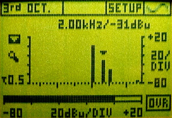
    11. The 3rd Octave analyzer can display the audible bandwidth from 20Hz to 20kHz in 31 bands. As mentioned, THD+N does not separate Distortion from Noise. "Harmonic Distortion" is a lack of sonic cleanliness relative to the input signal. Some vacuum tube gear is famous for its pleasing even-order (octave) harmonics. Input 1 kHz, for example, and push the device into its non-linear region (not hard clipping) and watch the — second harmonic (2kHz) pop up as in Figure-1.
    Figure-1: Even-order harmonics are generated by asymmetrical distortion as is common for some vacuum tube circuits. The cursor is over the second harmonic.
    Figure-2: Odd-order harmonics are created when opamps hard-clip, a 1kHz square wave produced this signature family of harmonics. The cursor is over the third harmonic.
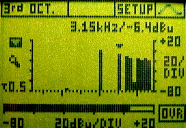
      The cursor can be moved to each of the 31 bands to confirm both frequency and amplitude, the latter in both dB and %. An opamp circuit in hard clipping will produce odd-order harmonics (square waves are made from these), the third harmonic to 1kHz is 3kHz. as in Figure-2.  See the Altec preamp specs in Table-1.

      The ML1 will also reveal unrelated content such as hum (fundamental and harmonics), hiss (the curve will vary with source topology, such as produced by amplifiers and analog tape recorders), plus the more common uses of spectrum analysis — the dreaded and completely frightening process of room / monitor-speaker evaluation.
       

    1. SCOPE

    2. If you read my article on trouble-shooting bad capacitors using square waves, the "oscilloscope-like" waveform display is the icing on the cake. Of course the perfect companion to the ML1 is the Minirator (the MR-1 is $139.95 @ http://www.mcmelectronics.com) reviewed in the ??? issue and featuring both sine and square waves. As with most LCD scopes, the ML1 does not have amazing resolution, further hampered by the 20kHz bandwidth, which softens square waves until 10kHz looks like a sine wave. That’s ok. About the cost of a cheap-but-real ‘scope alone, the ML1 is much more likely to see active duty, adding credibility to the overused phrase "bang-for-the-buck."
       

      GOOD DADA

      Reviewing the ML1 was a good brain exercise, emphasizing the relative ease of making a bad measurement compared to the work involved to acquire good data. That said, after reading this review, the people at Neutrik Test Instrumentsinformed me that an external 20dB attenuator is now available as an optional accessory. 

      Note-1: This will "pad" the output of the Minirator MR1 — or any oscillator — so that noise measurements would reflect the device under test and not the audio source.  It can also pad the input of the Minilyzer ML1 to extend its useful input range.) Otherwise, there is only one flaw. The maximum input of the ML1 is +20dBu, which is not high enough and easily compromised if the signal balance is not perfect.

      Note-2: Software updates are also available at the Neutrik Test Instruments web site.

      The ML1 is small enough to be kept in a control room or clipped to a belt — for those technicians on the move who are also looking to start a fashion trend. (PDAs might suddenly become less cool!)  Consider how many times you’ve returned to the scene of an audio crime only to find no suspects and no problem?  Now you can whip out this nifty little "geek tri-corder" whenever a problem occurs. By creating the Minilyzer, Neutrik Test Instruments have given more people the power to troubleshoot. The more you use it, the more you’ll understand that a little science never hurt anyone.

      This review was written for the December 2000 issue of MIX.  In the holiday spirit, be a good geek so that you can order both an ML1 and an MR1 without guild while sitting on the Fat Guy’s Lap.  (HINT: Don’t make any comments about the red suit or the funny smell coming from the beard.)  Then, look forward to a happy stocking hanging from your mantle bulging with "mini-toyz" on that magic day.
       

      I had too much fun reviewing the ML1 and I'm not giving it back!  If I get away with it, you’ll see more cool pictures all over this website.

      REVIEW SUMMARY

      NTI has a complete line of "expensive" test equipment of the type used by manufacturers, designers and specification certifiers.  I believe in this "mini" series from NTI because they provide useful, affordable tools for users who might otherwise not purchase anything.  In my goal to make technology more tangible, these tools provide the "link" between an instructive article and the curious end-user. 

      If, for example, I present an article on distortion, users can now do the same test, step by step with the same equipment.  The satisfaction of either confirming a suspicion and finding a problem or knowing that "all systems are go" is comforting.  That said, analog audio is easy to troubleshoot compared to digital audio.  Learning how to troubleshoot a system and correctly use test equipment are value-added skills.  That's why I am looking forward to reviewing the Digilyzer which should be an equally useful aid to unraveling the mysteries of digitized audio.

      Your Geek Buddy,

      Eddie Ciletti

      Click here for more information about this and other Neutrik Test Instruments.


    Return to Eddie's Homepage
    e-mail Eddie
    Go to the Tape Machine Directory

     
    SIDEBAR: The Ultimate Test

    In carpentry, the motto "Measure twice, cut once" couldn’t be more applicable than to the art of acquiring good data. Measuring NOMINAL level from a device is child’s play, but measuring signal at or into the noise floor is quite another. This is NOT a fault with the ML1.  I made several attempts until finally the results were consistent. You might not think much about "impedance," but when taking measurements, both the source and the destination impedance must be addressed.

    When measuring mic preamp performance at both minimum and maximum gain, the gain structure between it and the sound source (an oscillator) become quite critical. You cannot simply turn down the LEVEL at the oscillator because, in some cases, a buffer amplifier follows the Level control. The oscillator’s output amplifier has plenty of noise when looking down the high-gain barrel of a mic preamp. The top of Table-1 proves that reducing the level of the Minirator increases noise revealed in the THD+N measurement. Fortunately, the 3rd Octave analyzer helps to "see" the various noises.

    I fashioned a quickie attenuator between the oscillator and the preamp using a 1kohm pot across pin2 and pin3 of the female XLR. Pin3-f was connected to pin3-m, while the wiper from the pot was connected to pin2-m. With the Great River preamp set to max gain, I adjusted the trim pot so that preamp output fell just under +20dBu (+19.9 dBu) keeping in mind the ML1’s inability to tolerate anything higher. I then checked the attenuator output (-45.7 dBu) and calculated the gain to be 65.4dB.

    Once the gain was determined / confirmed, I removed the generator and attenuator and connected a source impedance that represented the average mic. I chose 150 ohms because it was used to create the preamp’s published specs. To calculate Equivalent Input Noise (EIN) = the noise floor + the gain setting. An older style signal-to-noise ratio (SN) measurement was also made. SN = the max output before clipping + the noise floor.

    End of sidebar.

     NEUTRIK TEST INSTRUMENTS
    Contact Information 
    NTI AG
       Im alten Riet 102
       9494 Schaan
       Principality of Liechtenstein
       Tel. +423 - 239 - 6060
       Fax +423 - 239 - 6089
       E-mail 

       contact : Mr. Schwizer Philipp


    Subsidiaries
    NTI Canada
       3520 Griffith Street
       St. Laurent
       Quebec H4T 1A7
       Tel. +1 - 514 - 344 5220
       Fax +1 - 514 - 344 5221
      E-mail

       contact : Mr. Vincent DeSouza


    Return to top of page
    Return to Home Page
    See More Test Equipment
    See other Reviews