Photo 1
©1998 and 1999
by Eddie Ciletti
updated with new linked page January '99
Error Messages? Click Below...
|
|
|
|
All adats -- blackface and XT -- regardless of brand name, are made by Alesis. This is an odd but generally good thing. The most common adat failure is not the rubber tire between the two reel tables but reassembly by inexperienced users. This article features hardware as well as software tips. To start, you should know that the transport for both the Original-adat and the adat-XT are nearly identical. Both machines suffer from Mode Switch Failure which is detailed in the article "Crunch a la Mode."
On the adat-XT, notice the reduced diameter of the Idler, the rubber tire that transfers motion from the motor to the reel tables. (Labeled "space ship" in Photo 1.) No longer made from a black synthetic rubber, it is now a nearly translucent shade of "tan." The less-obvious mechanical difference concerns the reel motor shaft, which is now larger and more "knurly."
The XT differs in three ways...
First, the XT's "cast" aluminum alloy chassis will not warp especially when compared to the old sheet metal case.
Second, nearly all of the electronic adjustments are now under
software control.
Later in this article, I'll show you how to recover from the two common
error messages. Click to go there now.
Third, all of the electronics have been redesigned.
This includes a more elaborate front panel and display, the System
Control board, the Audio Converters and even the Power Supply.
Meanwhile, let's check out the transport because it is the primary source of failure. This should come as no surprise because it is the "wear item," that is, the part that gets all of your abuse! First up: "how to avoid the common repair mistakes" plus two tips to silence two noisy rollers.
COMMON MISTAKE
Replacing the rubber idler on the Adat is a fairly simple task if you
don’t forget the order in which the pieces are reassembled. Photo1
will help those with short memories. The spring that goes on top
of the idler wants to reach orbit so be careful when sliding off the retaining
clip. Also note that the grooves on the rubber idler should be facing
the felt clutch on the mechanism.
Photo 1
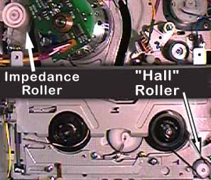
Some adat transports are noisier than others, particularly in fast-wind modes. One client described it as sort of a "hot rod" sound. The four possible culprits are the tape shell, a pair of white plastic rollers and/or the rotating head bearings. Photo 2 points to the rollers in question.
 ( Photo
2 )
( Photo
2 )Please note the modified flat-bladed screwdrivers used in the following
images. The tip has been reshaped into a "U" so that it fits around
the shaft. It has also been sanded "thin" and polished to be able
to fit under the washer. This is the same type of tool used to adjust
tape path on a DAT or DTRS transport.
| DESCRIPTION | PART NUMBER |
| Alesis "blackface" tire part number | |
| Alesis XT tire part number | 8-50-0053 |
| MCM "blackface" tire part number | 32-1495 |
| MCM XT tire part number | |
| Impedance Roller with Base Assembly | 7-14-0024 (revised as B 0103) ** |
| Magnetic "Hall Effect" Roller | 7-14-0018 |
| Belt for Hall Sensor Roller | 7-14-0017 |
| Mode Switch | 7-14-0019 |
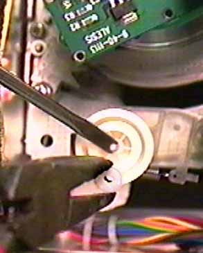
Noisy rollers should be replaced, but a little lubricant will shut 'em right up. Both must first be removed before lube can be applied. (Power down and unplug before removing the cover.) A white plastic cap is pressure fit over the metal shaft on which the Impedance Roller spins. Use a flat-blade screwdriver as a wedge to lift the cap. Then, gently squeeze the cap with a serrated-jaw long-nosed pliers alternating clock and anti-clockwise while gently pulling ( Photo 3).
 ( Photo 3.
Did I mention the concept of being gentle?)
Let the metal shaft enter a tube of "Lubriplate" (MCM tel:800-543-4330,
part number 20-1325) so that a light coating is left behind. Replace the
roller and gently slip on the cap until there is minimal vertical "play"
in the roller. Clean the roller with a lint-free cloth dampened with 99%
alcohol.
| GAINING ACCESS
To access the magnetic roller as well as some other parts and adjustments, it is necessary to lower the tape loading "elevator." This can be done two ways: via either software or very talented hands. The talented hand approach: As per Photo 4, position the right hand and fingers as shown to disengage the latches.
Power up, wait for the systemt o stabilize, then move the hand forward as if it were a tape. Power down as soon as the elevator is lowered. Remove the power cable. The soft approach: You can enter one of several TEST MODES by...
If, on some transports, the tape sensing latches keep the elevator from moving down, follow the mechanical portion of the "Talented Hands" procedure. |
CONFIRMING OPERATION
The "CAP" mode is designed to allow confirmation of mechanical operation. NOT ONLY is it possible to determine if the mode switch is in the proper position -- see note below -- but also that the reel- and capstan motors are functioning. PROCEDURE Assuming you have entered the "CAP" test mode, alternate between STOP and PLAY. Observe the movement of the pinch roller and the tension arm. In STOP: The Pinch Roller should be 1-mm from the capstan shaft and the Tension Arm should be "vertically centered" between the two vertical components immediately before and after (following the tape path). To be certain that the Mode Switch position is optimized, alternate between STOP and PLAY each time the switch location is changed. Doing so will allow the system controller to re-read the switch and reposition the mech to (hopefully) the correct position. Generally, the mode switch screw wants to be to the right >, if the adat is facing your tummy, or to the top as viewed in the photo to the left. Assuming the tension arm is not hung up (an "empty" load mechanism can cause this) and you can get it to "line up," there is another set screw, behind the take-up table, on the linkage that runacross the width of the mechanism. Loosen the set screw and adjust the linkage to set the pinch clearance in Stop mode. I use a 1mm hex key to measure clearance. All during this time, it should be possible to confirm that the reel motor is operational. By pressing FF, RW and FF, the reversing idler assembly (with the big rubber tire) should alternate position between each reel table. If it moves into position, the motor is good, but if either one of the reel tables fails to turn, there is friction in that table assembly (likely) or the brakes are always on (not likely). Click here for the description of the temporary fix. |
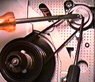
Once the magnetic roller is located, remove the belt. A split-plastic washer holds the roller in place. In years past this type of snap-washer was made of metal and formed into the shape of a "C" or "E." Extraction typically required the user to invoke the name of a deity, especially if the washer flew off into the Irish town of O'Blivion. If you've had too little or too much Cappuccino, take the machine to a qualified service center. Otherwise...
Photo 5 shows how two screwdrivers can be used to do the job. First, insert a jeweler's flat-bladed screwdriver into the split. A slight twist will open the washer, while the modified one to the left lifts it off the shaft. As this is done, put the jeweler's tip on the shaft to catch the washer as it pops off. If the washer achieves orbit, a spares kit is available from MCM electronics.
 ( Photo 5 )
Note that both reel tables may also need this treatment. The belt on the take-up table may keep it from chattering as will the small felt pad (not the back-tension felt) on the supply table. On the adat-XT, the pressure spring should have been removed. To test a "black-face" adat, lift the pad away from the table with a screwdriver. Remove the belt from the take-up table. Spin the tables by hand. If they chatter, it's time to lube.
“CAl brAC" stands for “calibrate brakes,” which — like an automobile
— need to be adjusted from time to time. Brake calibration on the
XT is accomplished through software and does not require a trip to a service
center. “Overshooting” is another indication that the brakes should
be re-calibrated. For example, the XT fast-winds and overshoots the
locate point, winds back and overshoots again, then winds forward and overshoots
— a shorter distance each time — until eventually reaching the locate point.
|
|
|
|
|
Obtain a standard ST-126 length
that has been completely formatted from beginning to end.
Use a non-essential tape. Do not use ST-180 or ST-60 lengths. |
|
|
With the power OFF, press REWIND
and FAST FORWARD during POWER-UP.
The display will read "CALIbrAt." |
|
|
Insert the formatted ST-126 tape
into the transport.
The XT will then FF the tape to the end then begin its routine. |
|
|
The XT will shuttle the tape back
and forth for about 5 minutes.
During this procedure, the tape will half-eject twice. This is normal. |
|
|
Assuming the tape, the reel motor and the brake solenoids are operational, the display should briefly read "PaSS" before fully ejecting the tape and returning to the "ADAT-XT" start up screen. If so, the brakes have now been re-calibrated. |
|
|
If the "CAL brAc" message re-appears,
check operation with another tape.
If the message persists, the unit must be professionally serviced. |
Numeric displays aren’t capable of accurately displaying all alpha characters. This particular message may look like “Cal P9,” but it actually is “Cal PG.” PG is the once-a-round pulse generated by a small magnet at the base of the head drum motor. It is used to align timing signals between the head stack and the control track head. When the PG Delay is not set properly, odds are that your XT will indicate that it is performing error correction via the “flashing sunburst.”
You can reset the PG setting by performing the following tasks:
|
|
|
|
|
Without a tape in the XT, lift the transport door and shine a flashlight into the unit. Notice the sticker on the back panel, to the right. Next to the field "PG" is a hand-written number — the PG value set by the factory technician. Write this number down. |
|
|
Turn the XT on while holding down track buttons 1 & 7. The display will read "0 SHIP *" |
|
|
Press PITCH UP three times. The display will read "3 P9 dLY *" |
| Press PLAY, the * will disappear, indicating that the PG Delay diagnostic has been initiated. | |
|
|
Press and hold PITCH UP or PITCH DOWN until the PG value agrees with the number written on the sticker inside the unit. |
|
|
Once that value has been reached, press and hold the EJECT button, then press REC to save the PG value. The display will then read "3 P9 dLY *" |
|
|
Press the EJECT button once more and the XT will enter its normal operation mode. |
|
|
Tapes recorded during the time when PG was improperly set should be backed up onto a new tape, AFTER the PG is reset, in order to preserve the audio without errors. |